Multimeter use how to test IGBT using Analog Multimeter and Digital Multimeter
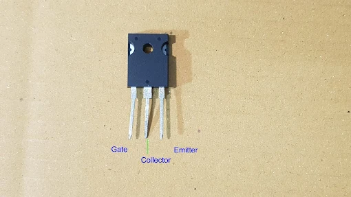
IGBT testing with multimeter IGBT has 3 legs , namely , Gate , collector and Emitter , Its working principle is input voltage control output current. we can use this basic bias to test whether it is a bad or good IGBT. Important note analog Multimeter use on this article it is a version that black test lead supply V+ and red test lead supply V- , when setting to resistance test function. Sample IGBT has Gate Collector and Emitter ( pin No. 1 2 3 respectively )
Step to test IGBT ON / OFF TESTING
1. Take IGBT part number to find leg function from datasheet.
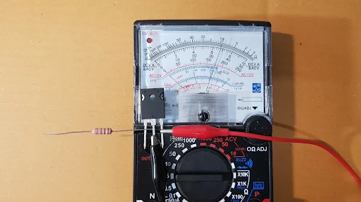
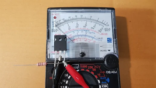
2. Connect test leads with IGBT leg as photo above.
3. Set analog multimeter to Rx10K as this range it will supply 9VDC from internal battery. 9VDC is high enough to bias gate leg so IGBT is working as ON state.
4. Use resistor's leg to temporarily connect between G leg and C leg ; the pointer's of multimeter move forward to low resistance as shown on photo.
5. After removing resistor leg the pointer 's of multimeter hold
the same position because IGBT is still working as ON state , this is for a good IGBT indication but the bad IGBT can not hold ON state so the multimeter's pointer move backward to ∞ position after removing resistor's leg.
6. Test OFF state , use resistor leg to temporarily connect between G leg and E leg.
the pointer's of multimeter that hold the ON state it does not hold any more , because V - from E leg will bias IGBT to OFF state.
6. Good IGBT can bias to ON state and OFF state but bad IGBT can not bais to ON and OFF state.
Bias Mosfet to ON , temporarily connect G and C leg
Good IGBT hold the ON state after removing resistor leg
, the pointer stay the same position but bad IGBT can not hold ON state.
Bias IGBT to OFF , temporarily connect G and E leg , the pointer ( ON state indicating ) will move backward to ∞ position or OFF state.
Step to check IGBT with Digital Multimeter.
1. Take IGBT part number to find leg function from datasheet.
2. Discharge 3 legs by shorting or connecting it together then do not touch the leg.
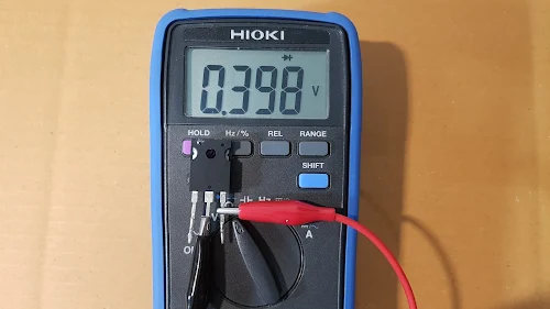
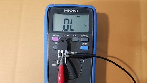
3. If there is a diode at C and E leg , set Digital Multimeter to diode test function ,
Good diode will show 0.5-0.8V voltage across it when forward bias.
and show "OL" when reversing bias.
Bad IGBT ( shorted ) will show 000V.
Bad IGBT ( open ) will show "OL" 2 times
4. If there is not a diode at C and E legs.
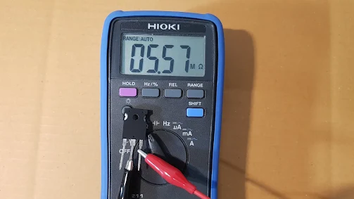
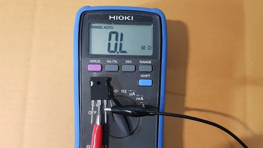
Set Digital Multimeter to resistor test function , the good IGBT has result ;
Good IGBT will show high resistance 1 time and show "OL" 1 time.
Bad mosfet ( short ) show 0 ohm 2 time.
Bad mosfet (Open) show "OL" 2 time.
Some model of IGBT has Diode at C-E leg
C-E leg testing that has Diode ( test as same as Diode)
Good IGBT show voltage drop 0.4-0.8V 1 time C-E leg testing ( reverse test lead ) that has Diode ( test as same as Diode)
Good IGBT show "OL" 1 time.C-E leg testing that IGBT has not Diode connected at C-E leg,
Good IGBT show high resistance 1 time
C-E leg testing ( reverse test lead ) that IGBT has not Diode connected at C-E leg ,
Good IGBT show "OL" 1 time.
5. Check G and C leg , connect test leads to G and C leg.
6. Set digital multimeter to resistance test function.
, do testing then switch test leads and do testing again.
Good IGBT will show "OL" 2 time because there is an insulator at gate leg junction so it is very very high resistance that multimeter can not measure that resistance ( show "OL" ).
Bad IGBT (gate leak ) will show some resistance.
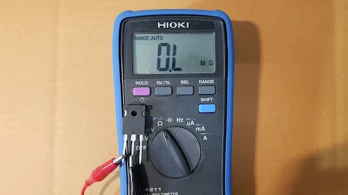
7. Check G and E leg , set digital multimeter to resistance test function.
8. Connect test lead to G and E leng , do testing then switch test leads and do testing again.
Good IGBT will show "OL" 2 time because there is an insulator at gate leg junction so it is very very high resistance that multimeter can not measure this resistance .
Bad IGBT ( gate leak ) will show some resistance.
G and C leg testing ,Good IGBT will show " OL" 2 time.
G and E leg testing ,Good IGBT will show "OL" 2 time.
8 Important Testing electronic device on this blog .
Testing electronic device IGBT testing SCR testing Triac Testing Check mosfet and more
Read on this page.
Read more .... all of testing , list of all article click here .
